
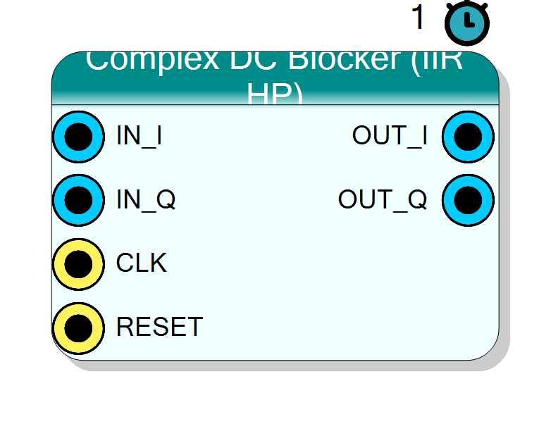
RF Complex DC Blocker (IIR HP)
First-order IIR high-pass (‘DC blocker’) that removes the DC / very-low- frequency component from a complex I/Q stream while passing everything above a cutoff set by the feedback coefficient alpha. Typical use: strip a residual DC offset (LO leakage, ADC bias) from baseband without a large FIR.
Introduction
The Complex DC Blocker (IIR HP) applies the classic first-order DC-block difference equation to each channel independently:
y[n] = x[n] - x[n-1] + alpha * y[n-1]
Its transfer function is
H(z) = (1 - z^-1) / (1 - alpha * z^-1)
a zero at DC (z = 1) that nulls the mean, and a pole at z = alpha just
inside it that sets how sharply the notch tapers. With alpha close to 1
the high-pass cutoff is very low, so only DC and the slowest drift are
removed and the rest of the signal passes essentially untouched.
The approximate 3 dB cutoff is
f_c / Fs ~= (1 - alpha) / (2*pi)
so e.g. alpha = 0.99 at Fs = 100 MHz gives a cutoff near 160 kHz.
Pin Description
x[n-1] and y[n-1] feedback registers; expect a settling transient
afterward.
Properties
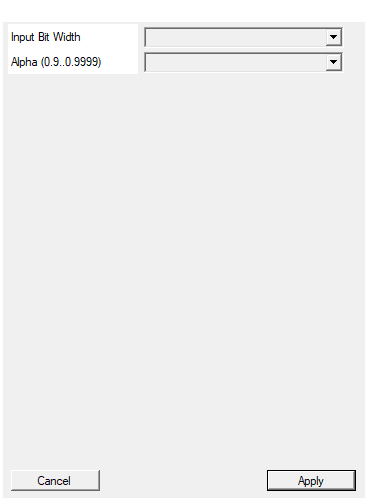
Bit width of each I/Q sample (signed). Output = InputSize+1.
Bit width of each signed I / Q input sample. Range 4 to 32, default 16. Output width =InputSize + 1.
Default: 16
Options: 4 5 6 7 8 9 10 11 12 13 14 15 16 17 18 19 20 21 22 23 24 25 26 27 28 29 30 31 32
IIR feedback coefficient. Closer to 1 = lower HP cutoff = slower DC tracking.
IIR feedback coefficient (pole location). Selectable from 0.90, 0.95, 0.98, 0.99, 0.995, 0.999, 0.9995, default 0.99. Closer to 1 = lower high-pass cutoff (f_c/Fs ~= (1-alpha)/(2*pi)) = slower DC tracking and a
narrower notch. Stored as round(alpha*2^15)/2^15.
Default: 0.99
Options: 0.90 0.95 0.98 0.99 0.995 0.999 0.9995
Usage
Stateful / feedback behaviour
This is an IIR / stateful filter. The C++ core keeps static feedback
registers per channel that carry the previous input and previous output:
static in_t x_prev_i, x_prev_q; // x[n-1]
static out_t y_prev_i, y_prev_q; // y[n-1] (the recursive feedback)
Each clock it forms y[n] = x[n] - x[n-1] + (alpha * y[n-1]) in a wide
accumulator, truncates to the output word, and stores it back as
y_prev for the next sample. The I and Q channels use identical,
independent filters (same alpha).
Alpha and the fixed-point shift
alpha is chosen from the property list (0.90 .. 0.9995) and converted by
the plugin to a fixed-point numerator:
alpha_num = round(alpha * 2^15) (ALPHA_SHIFT = 15)
The feedback term is computed as an integer multiply followed by an arithmetic right shift that undoes the scaling:
alpha * y[n-1] -> (alpha_num * y_prev) >> 15
So alpha_num / 32768 is the effective coefficient (e.g. 0.99 becomes
32440 / 32768). The >> 15 right-shift is the load-bearing operation: it
keeps the recursive product at the same scale as the samples. Alpha closer
to 1 = lower cutoff = slower DC tracking but a narrower notch.
Bit widths
Data is signed two’s complement.
IN_I,IN_Q: signedInputSizebits.OUT_I,OUT_Q: signedInputSize + 1bits (one guard bit for thex[n] - x[n-1]difference).- internal accumulator :
OutputSize + ALPHA_SHIFT + 2bits, wide enough to hold the pre-shift feedback product without overflow.
Reset behaviour
RESET is the HLS synchronous reset (ap_rst). On assertion the feedback
registers x_prev and y_prev clear to zero. Because the filter is
recursive, after reset (or a large step) the output shows a decaying
transient that settles with a time constant of roughly 1 / (1 - alpha)
samples before the DC notch is fully established.
Latency and throughput
#pragma HLS PIPELINE II=1: one sample pair per clock.- 1-clock latency.
- All ports use
ap_none. #pragma HLS INTERFACE ap_ctrl_none port=return: no block-level control.
Typical applications
- DC / LO-leakage removal on a down-converted baseband stream.
- ADC offset / bias cancellation without a big FIR.
- Drift / baseline-wander suppression ahead of a detector.
Resources & Timing
-
Latency: 1 clock cycle
-
Throughput: 1 sample per clock (II=1)
One multiplier per channel for the feedback term plus a couple of adders; the »15 shift rescales the recursive product. No BRAM. IIR / stateful (static x[n-1] and y[n-1] feedback registers). After reset or a step the output settles with time constant ~1/(1-alpha) samples.