
IIR Notch - II Order
Second-order IIR notch (band-stop) filter for removing specific frequencies. Uses high Q factor for narrow bandwidth rejection.
Introduction
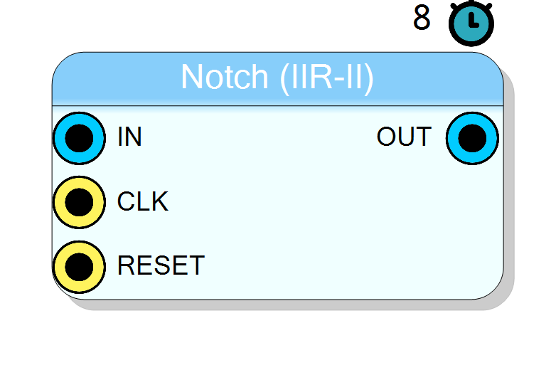
The IIR Notch - II Order block implements a second-order IIR notch filter operating in real time on FPGA. A notch filter (also known as band-stop or band-reject filter) attenuates a narrow frequency band while passing all other frequencies.
The filter is characterized by its center frequency and Q factor (quality factor), which determines the bandwidth of the notch.
Pin Description
Properties
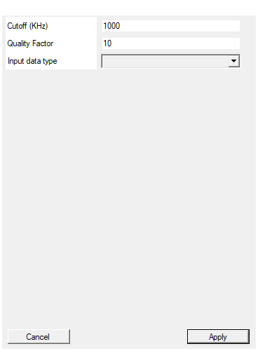
Set the filter pole/zero position according to the selected bandwidth in KHz
Default: 1000
Quality factor. Dimensionless parameter that characterizes notch filter -3 dB bandwidth bw relative to its center frequency, Q = w0/bw.
Quality factor (Q factor). Determines the bandwidth of the notch: BW = f0/Q. Higher values create narrower notches. Typical values: 10 to 100.Default: 10
Select input data type
Input data format selection. Available values: Unsigned 16 bit, Signed 17 bit, default Unsigned 16 bit.Default: UINT16
Options: UINT16 INT17
Usage
Notch Filter Characteristics
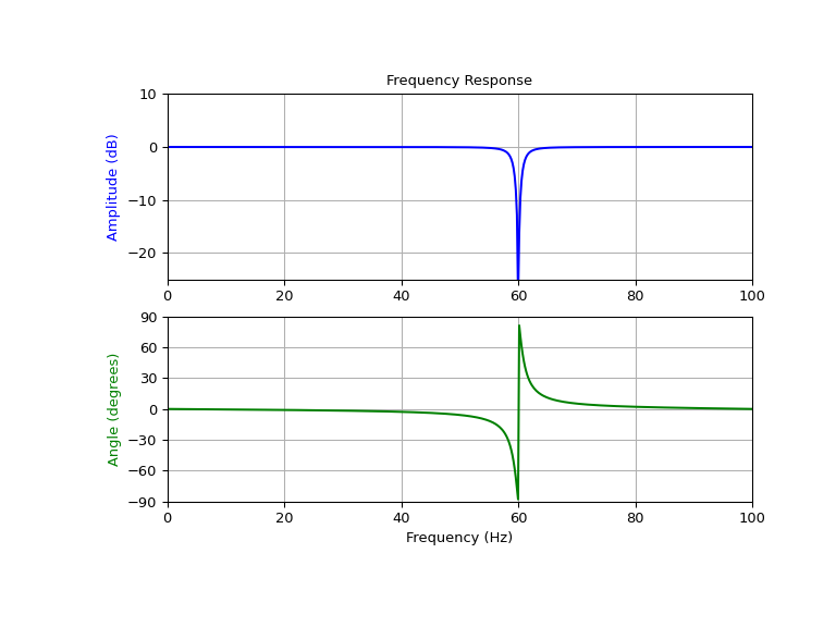
A notch filter creates a “notch” or dip in the frequency response at a specific frequency:
- Center Frequency: The frequency at maximum attenuation
- Q Factor: Quality factor that determines notch bandwidth (higher Q = narrower notch)
- Deep Attenuation: Strong rejection at center frequency
- Minimal Effect: Frequencies outside the notch pass unaffected
Bandwidth and Q Factor
The relationship between Q factor and bandwidth:
$$ BW = \frac{f_0}{Q} $$
where:
- BW: 3 dB bandwidth of the notch
- f0: Center frequency
- Q: Quality factor
Higher Q values create narrower, more selective notches. Typical Q values range from 10 to 100.
Scattered Lookahead Implementation
To enable real-time FPGA operation at full clock rate, the filter uses the Scattered Lookahead technique:

The standard IIR equation:
$$ y[n] = b_0 x[n] + b_1 x[n-1] + b_2 x[n-2] - a_1 y[n-1] - a_2 y[n-2] $$
Is transformed using scattered lookahead to:
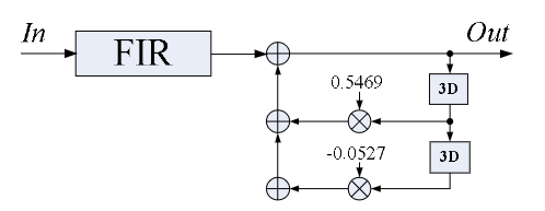
$$ y[j] = \sum_{k=0}^{6} b’_k x[j-k] - a’_3 y[j-3] - a’_6 y[j-6] $$
Reference: A universal look-ahead algorithm for pipelining IIR filters
Coefficient Calculation
SciCompiler automatically calculates the filter coefficients. The following Python code provides a reference implementation:
python
import numpy as np
from scipy import signal
def scattered_lookahead_transform(a):
A = np.array([[a[0], 0, 0, 0, 0, ],
[a[1], a[0], 0, 0, 0, ],
[a[2], a[1], a[0], 0, 0, ],
[0, 0, a[2], a[1], a[0], ],
[0, 0, 0, a[2], a[1], ]])
A_inv = np.linalg.inv(A)
D = A_inv * [1, 0, 0, 0, 0]
D1 = D[:,0]
D = D[:,0].reshape(-1, 1)
R = np.array([[ 0, a[2], a[1], a[0], 0, ],
[0, 0, 0, 0, a[2]]])
Qw = np.dot(R, D)
an = [1, Qw[0][0], Qw[1][0]]
bn = D1
return bn, an
fs = 250*1e6 # Sampling frequency
f0 = 10*1e6 # Notch center frequency
Q = 30 # Quality factor
w0 = f0/(fs/2)
b_z, a_z = signal.iirnotch(w0, Q)
print("original", b_z, a_z)
bn, an = scattered_lookahead_transform(a_z)
bq = np.convolve(bn, b_z)
aq = an
print("scattered", bq, aq)
Typical Applications
- Power line interference removal (50/60 Hz)
- Harmonic rejection
- Removing specific interfering frequencies
- Anti-resonance compensation in mechanical systems
Resources & Timing
- Latency: 8 clock cycles